
Frequently Asked Questions
- Using OpenVPN on the LTE520S Router - NEW
- 110v and 220v
- 8 Digit PIN
- Add another E200 Adapter to Your Network
- Add Guest Network on WRT300N-DX
- Block MAC Address on WRT300N-DX
- Calling Over Wi-Fi – WRT300N-DD
- Change Router Network Password
- Changed Settings and Now I Can’t Connect
- Connected to Router but No Internet
- Convert WRT300N-DD to dd-WRT
- DHCP Reservation – WRT300N-D6
- DirecTV DVR Won’t Connect to Wireless Router
- Easy Jack and VoIP
- Easy Jack LED Behavior
- Easy Jack May Not Co-exist With HomePlug Products
- Enable Call Waiting Caller ID
- Enable Remote Access to WRT300N-D6
- Enable Router Limits
- Enable UPnP – WRT500
- Firmware Updates
- Ghost Calls
- How Many Units Can Be Connected
- How to LTE BANDLOCK the LTE520
- Hum, Static, Buzz or Poor Voice Quality on Easy Jack
- Isolate Guest SSID From Network
- LAN and WAN
- Link Easy Jack Base Unit with Extension Unit
- Mobile Device Wi-Fi Shows "Weak Security" or "Not Secure"
- Multiple Circuit Panels
- No Caller ID on TV Screen
- No Phone Signal – Easy Jack PX211
- No Wireless Broadcast
- Port Forwarding
- Port Forwarding – WRT150N
- Port Forwarding Example for the WRT300N-DD
- Port Forwarding on the WRT300N-D6
- Power Light Is Red – WRT300N-DD
- Power Outage
- Power Outage – Easy Jack
- Power Strip, Surge Suppressor, GFI Outlet
- Problem Connecting or Getting Internet after Changing Settings
- Pulse and Tone Telephones – Easy Jack
- Range of Power Line Products
- Repeater (Bridge) Mode – VWRT510, WRT500
- Repeater Mode – WRT300N-D6
- Repeater Mode – WRT300N-DD
- Repeater Mode – WRT300N-DX
- Set Up AC1000 or AC1200 as Repeater over Ethernet
- Set Up Guest Network
- Set Up Managed Router as Wi-Fi Repeater
- Set Up ReadyNet Managed Routers in Bridge Mode
- Set up Wi-Fi Repeater so Repeater has Addressable IP
- Setting/Changing Security – WRT300N-DD
- Slow or Intermittent Internet Speed
- Unable to Connect to Router
- Units Don’t Communicate
- Using Easy Jack with DSL High-speed Internet
- Using the USB Port
- VoIP Call Disconnects, Ghost Calls
- VoIP Rings Spontaneously
- Wi-Max and ReadyNet Routers
- WPS Disabled By Default
- WRT300N-D6 MAC Filter Configuration
110v and 220v
The Easy Jack works only with 110v. It does not have a switching power supply. The E200, EN200, EN500, and E4PS200 have switching power supplies.
8 Digit PIN
When setting up a new router for the first time, your computer may ask for an 8 digit PIN number. It’s your computer’s Microsoft operating system trying to set up WPS. ReadyNet does not consider WPS as secure as other security methods to protect your network so has disabled WPS by default. After selecting the network name (SSID) to which you want to connect, a small screen will pop up asking if you want to set up your network.

Click on “Connect to the network without setting it up”. Another screen will pop up asking for your passphrase or network key. Type in the passphrase shown in the user manual or on the label on the bottom of your router and click on “Connect”.
Add another E200 Adapter to Your Network
To add a new adapter (E200C) to a network of two adapters (E200A and E200B), do the following:
- Press and hold the Security button on E200C for 10 seconds. Release it when the Power light flashes. The password to E200C has just been erased. It must now be linked to your network to adopt the new network security key.
- Press and hold the security button on E200A for 2 seconds. The Power light on E200A starts to flash.
- Within 120 seconds after the Power light on E200A starts to flash, press and hold the security button on E200C for 2 seconds then release.
- E200A, E200B, and E200C are now networked to each other.
Add Guest Network on WRT300N-DX
- Log into the web interface of the router.
- Navigate to Wireless > Basic and add your Guest SSID in the Guest Wi-Fi 1 field, then click ‘Save’ at the bottom of the page.

3. After the router reboots, navigate to Wireless > Security and setup Wi-Fi security as shown below, then click ‘Apply’.

Block MAC Address on WRT300N-DX
Navigate to Firewall > MAC/IP filtering and set
– MAC/IP Port Filtering > Enable
– Default Policy => Accepted
– Click Apply
– Add the MAC to be blocked in the “Source MAC Address” field.
– Click Apply.
Restart.

Calling Over Wi-Fi – WRT300N-DD
Use the following steps to configure the WRT300N-DD router to function with calling over WI-Fi offered by cellular telephone companies.
- Log in to the DD user interface and navigate to Wireless>Advanced>click button WMM Configuration.
- In the window that pops open, change the first table, which is titled WMM Parameters of Access Point, as follows (see screen shot below):
- Change the value of the column CWMin and row AC_VO to 1
- Change the value of the column CWMAX and row AC_VO to 3

- Click the Apply button and the router will now save these settings and reboot.
Change Router Network Password
Connect your computer to a LAN port on the router using an Ethernet cable. Log into the router’s user interface by bringing up a browser and typing 192.168.11.1 (192.168.1.1 for the WRT300N-DD) into the browser’s URL field. The login name and password are located in the QIG and on the sticker on the bottom of the router. On some WRT300N-D6 routers the user password was inadvertently left off the sticker; it is pz938qd6. Go to Wireless; then Security. You will be able to change the password on this page. Instructions for each router can be found in the QIG sent with each router and in the Support section of this website.
Changed Settings and Now I Can’t Connect
Sometimes when settings are changed there are unintentional changes that cause connection problems. The following steps may help restore connections.
1 – Verify cables are in the correct ports on the ReadyNet router (Internet Service Provider modem is plugged into the blue/WAN port on the router). If not, change and test for Internet.
2 – Verify your Internet service is active by plugging your computer directly into your ISP’s modem and surfing the Internet. If no Internet, contact your ISP.
3 – Reconnect all Ethernet cables and connect your computer to one of the yellow/LAN ports on the ReadyNet router by Ethernet cable.
4 – Reset the ReadyNet router to factory defaults by pressing the reset button on the back of the router (press for 15 seconds and wait for 1 minute while router reboots). Then test for Internet. If successful, you can change the network name and passphrase if desired.
5 – When connecting wirelessly, you may need to “Forget the Network” on your wireless device to clear the cached settings for that network, and then input the network’s passphrase.
Connected to Router but No Internet
- When two routers are in a daisy chain configuration, they cannot have the same LAN IP address or one of them won’t work.
- Make sure the Ethernet cable from your Internet Service Provider’s modem is connected to the WAN port on the router.
- Check WAN IP address on the router user interface Status page. If there is no WAN IP address, there may be an IP address conflict with the Service Provider modem or another device on the network. Change the IP address to 192.168.10.1, reboot your computer, disconnect Ethernet cable from computer, then try to connect wirelessly and surf.
- If no WAN IP address, you may need to set up MAC Clone (for the WRT300N-DD go to WAN>Dynamic IP Setting) in the router’s user interface.
Convert WRT300N-DD to dd-WRT
To change stock WRT300N-DD firmware to DD-WRT do the following:
- Make sure the WR300N-DD router is connected to the internet via the WAN port
- Log into the router (default username and password are admin) with your browser at the address http://192.168.1.1
- Click Advanced Settings.
- Click System Command.
- In the Command field type (copy-n-paste) the following command:
wget -O /var/firmware http://www.readynetsolutions.com/wp-content/uploads/2014/07/firmware.bin ; mtd_write -r write /var/firmware Kernel
Click the Apply button.
- Wait about 5 minutes and then restart your browser and navigate again to http://192.168.1.1
- The router will now be running dd-WRT.
- The default username and password for dd-WRT are root and admin.
DHCP Reservation – WRT300N-D6
Here are the steps for DHCP reservation on the WRT300N-D6:
- Log in to the D6 router’s user interface.
- Navigate to Setup>Local Network.
- In the DHCP Static IP Configuration section, add the IP address and the MAC address. The IP address must be between 192.168.11.100 – 192.168.11.200. The MAC address of the device can be obtained from Status>Active Clients Table provided the device is connected to the router.
- Click Add.
- Reboot the device so it will re-acquire the newly configured Static IP.
DirecTV DVR Won’t Connect to Wireless Router
When connecting your DVR to a wireless network, the DVR will save the network connection settings. Changing to another Internet Service Provider, replacing your Wi-Fi router, or changing settings on your wireless router such as SSID (network name) or passphrase may create an error condition (86-883) when trying to connect your DVR to your wireless network. You may need to reset your DVR network connections to factory default.
From http://forums.directv.com/thread/11252257 – “On your DirecTV DVR press: MENU ➜ SETTINGS & HELP ➜ SETTINGS ➜ NETWORK SET UP ➜ RESTORE DEFAULTS ➜ CONNECT NOW ➜ GET CONNECTED ➜ WIRELESS. The receiver will then scan for Wi-Fi networks and should find yours. Once it finds your SSID, select your network name. If your network is secured, it will ask you to type in your password. If successful, you will get a message that says ‘congratulations, your receiver is connected to the Internet’. Note that your SSID and/or password cannot have any spaces and/or special characters.”
Easy Jack and VoIP
You can use the Easy Jack with VoIP service if the service provider’s modem has an RJ11 (telephone) port. Connecting the Easy Jack base unit to the RJ11 port on the service provider’s modem will then provide access to the telephone signal at any electrical outlet when using an Easy Jack extension unit. The PX211D is designed for data so if you want to use it for voice, you may experience some static on the line. The PX211V is designed for voice and may provide better voice quality.
Easy Jack LED Behavior
Base Adapter LED
- Solid Green – Connected to power line and connected to phone line
- Blinking Green (slow) – System in use
- Blinking Green (fast) – Incoming call ring
- Solid Red – Phone line not connected or phone line in use
- Blinking Red – Programming mode with new security code selected
- Blinking Orange – Security code programming mode for linking Extension Adapters
Extension Adapter LED
- Solid Green – Connected to power line and linked to Base Adapter
- Blinking Green (slow) – System in use
- Blinking Green (fast) – Incoming call ring
- Solid Red – Not linked to Base Adapter
Easy Jack May Not Co-exist With HomePlug Products
Easy Jack units broadcast in the 2.8-4.3Mhz frequency range. Products designed to standards of the HomePlug Appliance broadcast in the 2-28Mhz frequency range. HomePlug Alliance standards apply to high-speed, broadband products usually associated with Ethernet connections. Because of this overlap in frequency ranges, HomePlug products can interfere with Easy Jack signals when the HomePlug products are broadcasting. Neither Easy Jack nor HomePlug products broadcast all the time. The E200, EN200, EN500, E4PS200 are HomePlug standard products. Easy Jack units do not usually interfere with HomePlug units because of HomePlug’s frequency hopping capabilities.
Enable Call Waiting Caller ID
To enable Call Waiting Caller ID, in the User Interface navigate to FXS1/FXS2 > Preferences, then scroll to he bottom of the screen to Miscellaneous.

Enable Remote Access to WRT300N-D6
Remote Access
To enable remote access to the router’s user interface, log into the router’s user interface, navigate to Advanced > Access Control List. Select ‘web’, then click ‘Add’.

Once ‘Add’ is selected, remote access is enabled and the user interface screen will look like this.

Enable Router Limits
For Router Limits subscription service to work on ReadyNet routers (AC1000M, AC1000MS, AC1100MSF, AC1200M, AC1200MS), it needs to be enabled in the router’s user interface. If you bought your ReadyNet router from Router Limits, it comes with Router Limits enabled. There are also several Internet service providers who are able to remotely enable Router Limits so you may want to check with your service provider. If Router Limits has not been enabled and your Internet service provider is not able to do this for you, you will need to log into the user interface (UI) of the router. Type 192.168.11.1 in the URL field of your web browser and log in with the user name and password on the bottom of the router. Once in the UI, follow these steps to enable Router Limits.
From within the router’s UI (192.168.11.1):
1) Click the “Security” tab
2) Click the “Router Limits” tab
3) Choose “Enabled” in the drop-down
4) Click “Save” & “Reboot”
5) Click “Activate”

If Router Limits is enabled in your ReadyNet router and you need assistance with your Router Limits service, please contact Router Limits.
Enable UPnP – WRT500
To enable UPnP on the WRT500, do the following:
- Log in to the web interface of the router and navigate to Application>UPnP.
- Click on Enable UPnP.
- Click on Save.
- Click on Reboot.
Firmware Updates
Periodically there are updates to router firmware. These updates are posted in the Support section on ReadyNet’s website (www.readynetsolutions.com) by router model. You may have the latest version of firmware on your router. Log in to the router’s user interface and check the Status page for the version on your router. If you do not have the latest version, download the latest firmware version to your desktop then navigate to Management or Administration to upload the firmware.
Ghost Calls
To prevent ghost calls, adjust the settings in the red rectangle as shown below. These settings are found in SIP Account>Line {n}>Advanced.

These settings instruct the device to only accept INVITEs from the defined IP. The device will ignore scripts that run which probe all publicly accessible IPs for open port 5060. Such scripts cause the ghost call ring.
Once these settings are added there should be no unnecessary rings and security will be enhanced.
How Many Units Can Be Connected
You can connect up to 8 Easy Jack extensions to one base unit. Only use one Easy Jack base unit per home and the Easy Jack system will only work with one telephone line. Easy Jack base units in the same home will compete with each other, sometimes canceling each other out.
You can connect up to 64 E200 units, though for best performance we recommend you limit the number of units in the network to less than 20.
You can connect up to 8 EN200s or EN500s in a network.
How to LTE BANDLOCK the LTE520
The following are steps to enable LTE BANDLOCK on the LTE520:
- In the web GUI, set “Network -> LTE -> Internet Connection” = “4G Only”
- Then select the desired Band on “Network -> LTE -> Internet Connection -> BANDLOCK” option.
- Scroll down to Click “Save & Apply”
- Wait 2-3 mins for the modem to connect to the new Band.
NOTE: Please ensure that your browser does not autofill the “Username” or “Password” fields. These fields should be left blank unless specifically instructed to fill them in by the LTE network operator. Incorrectly setting the Username and Password will cause the router to no longer connect to the LTE network.
Hum, Static, Buzz or Poor Voice Quality on Easy Jack
The Easy Jack is designed for data so it is common to experience a buzz, hum, or static when using it for voice. Sometimes quality can be improved by relocating either the base or extension or both to a different electrical outlet. Quality of the communication signal between units can be affected by what else is plugged in and operating in your home. Also, make sure the units are not in power strips or GFI outlets.
Isolate Guest SSID From Network
You can isolate those devices connecting to a ‘Guest’ SSID from your network by checking the following boxes:
1) Wireless > Basic > AP Isolation
2) Wireless > Basic > MBSSID AP Isolation
3) When these boxes are checked, the ‘Isolated’ setting for individual SSIDs will be automatically checked.

4) Now Reboot.
LAN and WAN
The router has two interfaces, WAN and LAN; each with a different MAC address. LAN is a bridged grouping of the 4 LAN Ethernet ports and the Wi-Fi interface. WAN and LAN have distinct MAC addresses and they are sequential. That is layer 2 of the OSI model. Layer 3 is where IP addresses come into play. By default, the WAN port is set for DHCP. If not connected, there is no IP address, Subnet or Gateway. However, for the LAN side the Layer 3 part is configured. If you go to LAN>LAN Settings you see that the LAN interface is statically assigned its IP and Subnet Mask. In addition, there is also a DHCP server running on the LAN interface and assigning IP addresses from the same network as that of the LAN IP address. This allows you to connect to one of the LAN ports or via Wi-Fi and access the web interface of the router. That is why you see 4 categories with information in the LAN section of the Status page.
To get a list of the devices connected to the LAN of the router, go to LAN>DHCP Server and look at the DHCP client list table.
Link Easy Jack Base Unit with Extension Unit
The best way to link the units is to put them in the same electrical outlet (turn extension unit upside down), then press and release the button on the base unit. It will start flashing orange. Then press the button on the extension unit. It should start flashing green. If so, the units are linked and you can press the buttons once more on each unit to take them out of programming mode.
Mobile Device Wi-Fi Shows "Weak Security" or "Not Secure"
This message shows up after updating to iOS 14.
To prevent this warning from showing up, login to your router and navigate to: 'Wireless 2.4GHz' -> 'Wireless Security'.
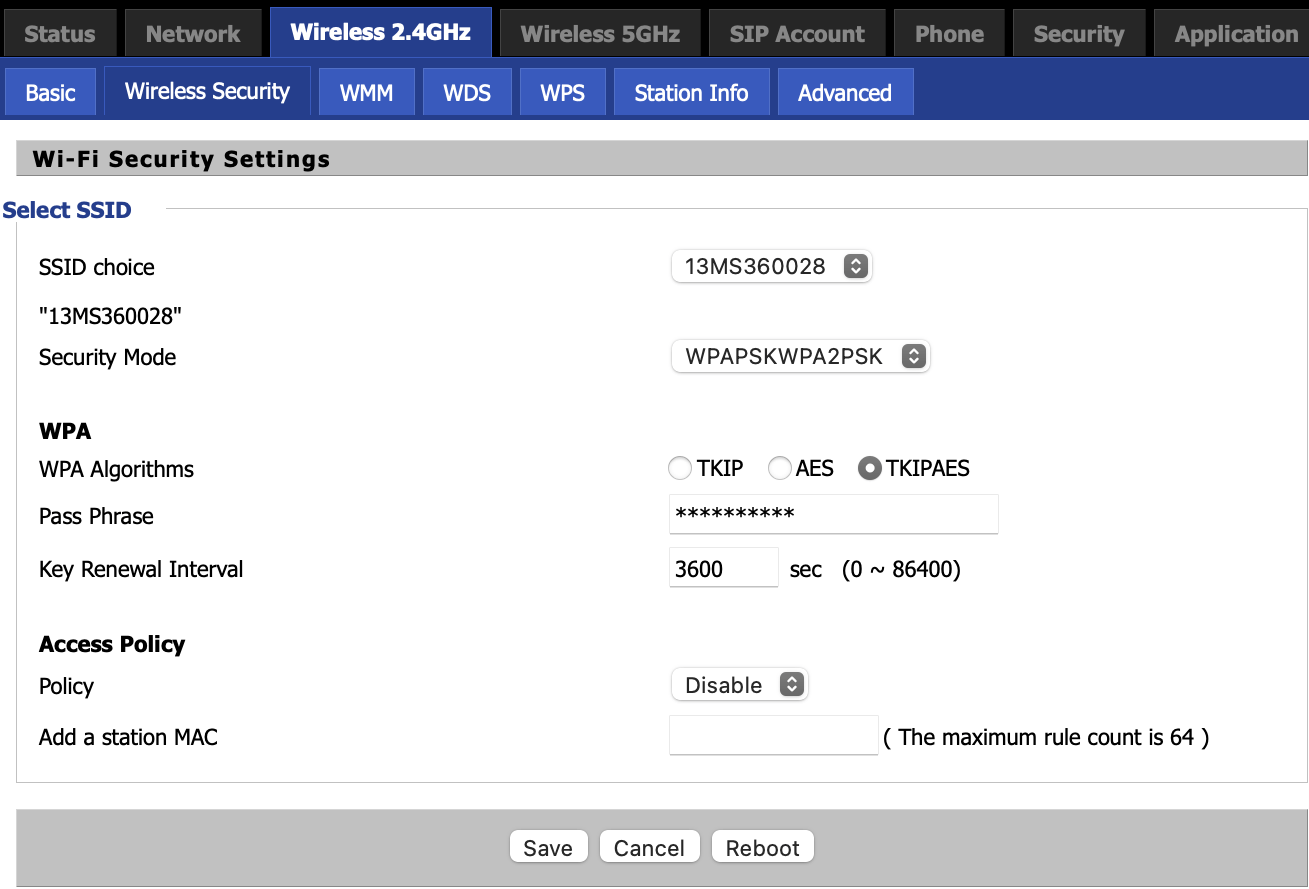
1) For 'Security Mode' change 'WPAPSKWPA2PSK' to 'WPA2-PSK'
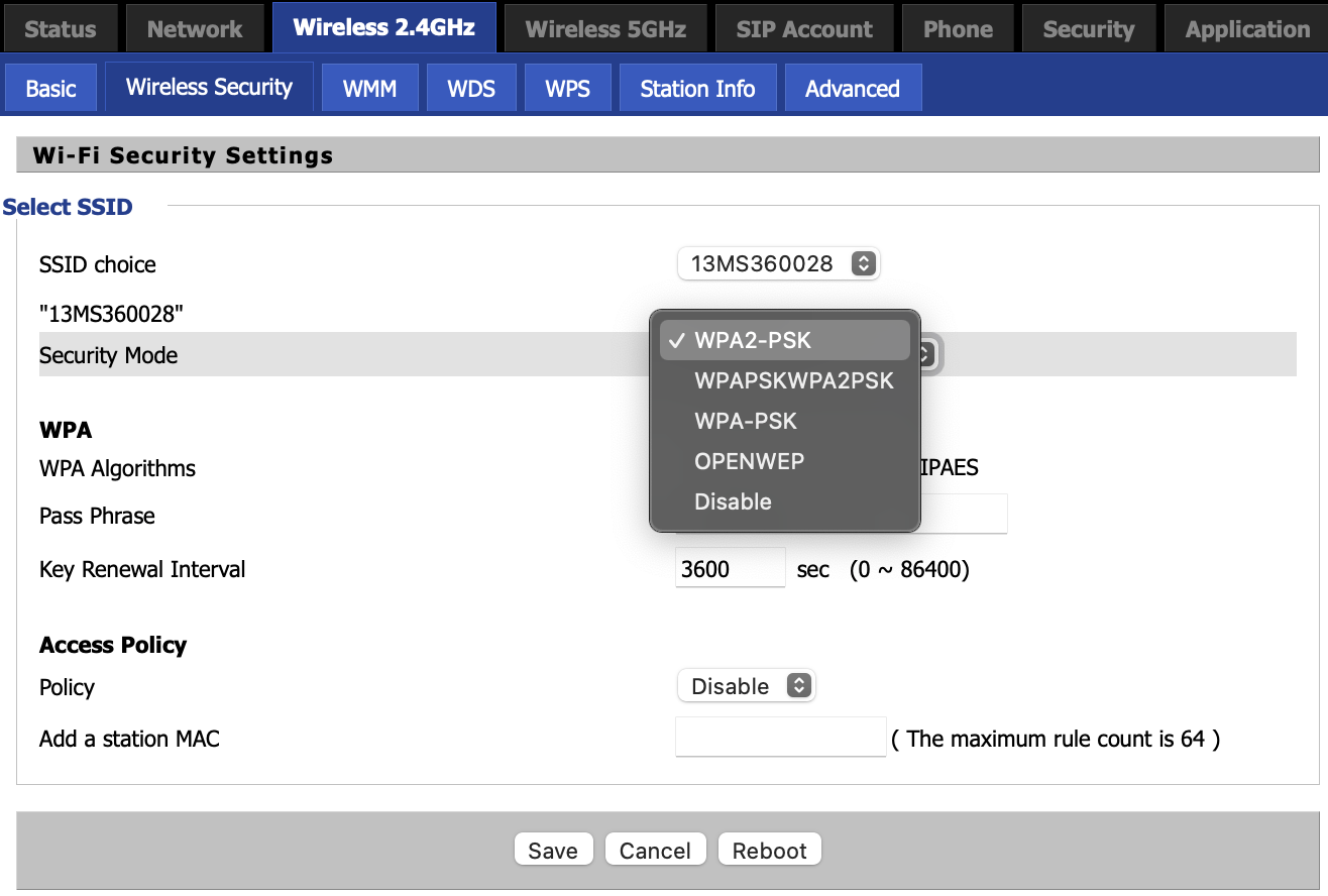
2) For 'WPA Algorithms' change 'TKIPAES' to 'AES'
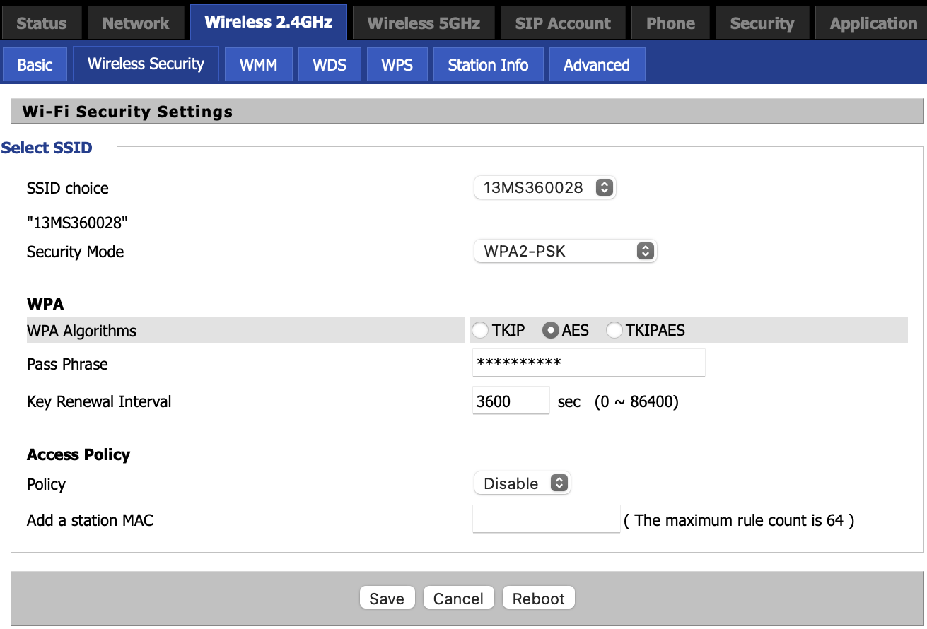
3) Click 'Save'
4) Next, navigate to: 'Wireless 5GHz' -> 'Wireless Security' and repeat steps 1 through 3.
5) After saving, click 'Reboot'
Multiple Circuit Panels
Power Line Carrier (PLC) products will work reliably if connected in electrical outlets wired to the same circuit panel. If you have multiple circuit panels, units are not likely to communicate if they are plugged into electrical outlets wired to different circuit panels.
No Caller ID on TV Screen
It is not uncommon for Caller ID display to come and go with the Easy Jack units. Electrical wiring impedance affects the units and will change depending on conditions in the home. For instance, a plasma TV emits enough impedance to disrupt the Easy Jack signal in the right circumstances. Even with dial tone and ability to use phone on the extension unit, there may be times when Caller ID may not display on your TV screen when your set-top box is connected to the Easy Jack.
With satellite TV service providers, there is usually a Caller ID menu option which must be activated for Caller ID to appear on your screen. Verify that this option is selected.
DISH satellite has installed DISHCOMM units with some of its installations. DISHCOMM is PLC technology that facilitates communication between multiple set-top boxes in one home. DISHCOMM units do not communicate with Easy Jack units. For the Easy Jack to communicate properly, an Easy Jack base unit and an Easy Jack extension unit must installed.
No Phone Signal – Easy Jack PX211
First verify that your phone service is active by connecting a phone directly to the wall phone jack you are connecting to the Easy Jack. If there is no dial tone, the problem may be with the wiring in your home or your telephone service provider. The LED on the base unit remains red until it is connected to an active phone line.
No Wireless Broadcast
If the router network name (SSID) is not visible to your wireless devices (computer, tablet, smart phone, etc.), the broadcast function of the router may have been turned off. Check the router LED display panel for the Wi-Fi or Wireless light. If not on, log in to the user interface, navigate to Wireless and verify the broadcast and Wi-Fi functions are turned on.
Port Forwarding
A public WAN IP address is needed for port forwarding to work. If you are unsure if your WAN IP address is public or private, contact your Internet Service Provider. If the WAN IP is not a public IP, it, and all internal devices connected to the router, will not be available to the outside world. If it is a public WAN IP address, all devices will be available to the outside world. The following are some common private IP ranges:
192.168.0.0 – 192.168.255.255
172.16.0.0 – 172.31.255.255
10.0.0.0 – 10.255.255.255
100.64.0.0 – 100.127.255.255 [This range is used by HughesNet for Carrier Grade NAT]
Once in the user interface, navigate to the Network tab and then click the Port Forward tab. Enter values for Name, Protocol, External Port, Internal Address, and Internal Port. Then click Save & Apply. Any requests that come to the router’s WAN connection on the specified port will be forwarded to the IP address and port specified on the LAN side.
Application Port Forwarding for the WRT500, VWRT510, VWRT520, AC1200M and AC1200MS
Login to your router and navigate to Network > Port Forward and in the “Port Forward” section add one port forward rule for each port that you need opened. Note that you also have to enter the IP address of the device to which you want the port to be forwarded.

Xbox Live requires the following ports to be open:
- Port 88 (UDP)
- Port 3074 (UDP and TCP)
- Port 53 (UDP and TCP)
- Port 80 (TCP)
- Port 500 (UDP)
- UDP Port 3544 (UDP)
- UDP Port 4500 (UDP)
Server Port Forwarding for the WRT500, VWRT510, VWRT520, AC1200M and AC1200MS
If you’d like to run a server on your internal network and have it accessible for the outside, then you need to add a “Virtual Server” rule as in the image below. In this example we are running a server on the local IP of 192.168.11.100 which has a web server ‘listening’ on port 81. In order to expose this web server to devices on the WAN side of the router add this following rule.

After you click ‘Apply’ and reboot your router, you can access the internal web server from the WAN side with the URL, http://WAN_IP:8888/ where WAN_IP is replaced with the WAN IP of your router (Status > Network Status > IP Address).
Port Forwarding – WRT150N
Below is a screen shot of the set up for Port Forwarding for Black Ops II on the WRT150N.

Port Forwarding Example for the WRT300N-DD
Here are instructions for setting up port forwarding in the WRT300N-DD.
- Log in to the router user interface.
- Navigate to Advanced Settings>Port Forwarding.
- In the first table, which is Port Forwarding, enter the first port forwarding. The IP address to enter is the IP address of your device (Xbox, PS3, etc.). You can find it in the Network settings of the device.
- Click Apply.
- Repeat steps 3 and 4 for each of the port forwards you need.
The screen shot below shows the port forwarding set up on a DD router for a device on the internal network on 192.168.11.100 for port 81.

To access port 81 running on the internal IP address from the outside (WAN side), find your WAN IP (Status>WAN IP Address) and then simply use http://WAN_IP:81/(replacing WAN_IP with Status>WAN IP Address).
Port Forwarding on the WRT300N-D6
Connect your device to the wireless router and use the following steps to set up port forwarding. You will need to know the protocol (TCP or UDP) and the the port or port ranges that need to be forwarded.
Step 1) First assign your device a static IP by navigating to Setup>Local Network>DHCP Static IP Configuration and inputting a static IP such as 192.168.11.100 and your MAC address. Then click ‘Update’.

Step 2) Navigate to Advanced>Virtual Server to input the ports to be forwarded. In the image below, we are adding the 10040-10060 range as TCP to be forwarded to the local IP address 192.168.11.100 (statically assigned in Step 1 above). Click ‘Apply Changes’.

For connecting a PS3 or PS4, Sony indicates you will need to forward the following ports:
- TCP Ports: 10050, 10051, 10040 – 10060
- UDP Ports: 50000 – 60000
Enter these port ranges as indicated in Step 2 above. They will be displayed as shown below

Power Light Is Red – WRT300N-DD
When the WRT300N-DD is turned on, the PWR LED is red.
Power Outage
Power outages can cause some routers to reset to factory default. Use factory default settings shown on the bottom of the router or in the QIG to connect to the router. Once connected, you can log in to the user interface and change the network name, password or other settings as needed.
Power Outage – Easy Jack
Power outages can cause Easy Jack units to become out of sync with each other. Move the extension unit close to the base unit (in the same electrical outlet if possible) and go through the sync process (press button on side of base unit, then press button on side of extension unit). Base unit will flash orange and extension unit will flash green – units are synced so press buttons again to take out of the program mode.
Power Strip, Surge Suppressor, GFI Outlet
The number one reason users have trouble with Power Line Carrier product connections is they plug one or more of the units into a power strip, surge suppressor, or GFI electrical outlet.
Problem Connecting or Getting Internet after Changing Settings
After changing router settings, it sometimes helps to reboot the router. You may also need to reboot your computer. In some instances, you may need to reboot your Internet Service Provider modem or access device.
Pulse and Tone Telephones – Easy Jack
Easy Jack units work with both tone and pulse telephones.
Range of Power Line Products
Power Line Carrier (PLC) products transmit over the electrical wiring so distance is dependent on the electrical wiring and what electrical equipment is operating in the location. They will generally transmit up to 300 feet. Moving the units to different electrical outlets may improve performance.
Repeater (Bridge) Mode – VWRT510, WRT500
Use the following steps to set up the WRT500 in repeater (bridge) mode.
First reset the WRT500 router to factory default settings (Admin -> Manage -> Factory Default -> Reboot), then navigate as follows:
1) Network -> WAN -> INTERNET -> Bridge -> Save
2) Network -> LAN ->
- 1) change IP to an unused IP of the primary AP’s LAN subnet. For example, if the DHCP range of the primary AP is 192.168.1.100-200, choose 192.168.1.222 for the LAN IP.
- 2) set Local DHCP server to Disable and click Save.
3) Wireless -> Wireless Connection Mode -> Repeater -> Save
4) Wireless -> Repeater ->
- 1) refresh and Click to highlight your primary AP, then ‘Connect’.
- 2) enter the Passphrase of the Primary AP and click ‘OK’
5) Reboot the router.
6) Wait about 1 minute then renew the IP of your PC.
Repeater Mode – WRT300N-D6
Set Up the ReadyNet WRT300N-D6 as a Repeater
You can use one or more WRT300N-D6 routers as repeaters with a WRT300N-D6 router as the base. Just follow these simple instructions.
Base Router
- Power up the router you will use as the base station (Base Router). It will be connected to your Internet access point. Connect it to the Internet and make sure it can access and surf the Internet.
Repeater Router
Log into the User Interface
- Power up the WRT300N-D6 you want to set up as a repeater (Repeater Router). Connect it to your PC or MAC by plugging an Ethernet cable into one of the LAN (yellow-colored) ports on the back of the router and into the Ethernet port on your computer.
- Log into the user interface of the Repeater Router by typing ‘192.168.11.1’ into the URL address field in your computer’s Internet browser. A login box will appear. The User ID is ‘admin’ and the password is ‘pz938qd6’.
Change Repeater’s IP Address
- Click on Setup -> Local Network. Change the IP address from 192.168.11.1 to 192.168.11.222 as indicated in Figure 1.
- Click ‘Apply Changes’.
- Click ‘OK’ on the popup window.
- Wait about 40 seconds and then click the link.

Enable Repeater Function
- Click Wireless -> Wireless Then check the ‘Repeater Enabled’ checkbox and click ‘Site Survey’ as indicated in Figure 2.
- Click “OK’ on the popup window.
- Click “OK’ on the second popup window.

- You will now see the results of the wireless site survey as shown in Figure 3. Click the ‘Select’ checkbox corresponding to the Base Router and click ’Next’.

- Select the Encryption and Pre-Shared Key of the Base Router and click ‘Apply’. The default settings for the WRT300N-D6 are shown in Figure 4.

- Navigate to ‘Status’ -> ‘Device Info’ and wait for the ‘Repeater Status’ to say “Connected” as indicated in Figure 5. Click ‘Refresh’ at the bottom of the page or wait 1 minute for the page to reload automatically. ‘DHCP Server’ should be disabled as indicated in Figure 5. If not, navigate to ‘Setup’ -> ‘Local Network’ and select ‘None’ in ‘DHCP Mode’ under ‘DHCP Server Settings’ and click ‘Apply’.

- Once, the ‘Repeater Status’ field says connected, renew the IP address of the PC or MAC you are using (or restart the PC or MAC) so that it will get its IP address from the Base Router and update its Gateway address.
- Check that you can access the Internet after renewing your IP address. If you can access the Internet, the Repeater Router has been successfully set up.
- If you want to change the SSID of the Repeater Router so it is different from that of the Base Repeater, navigate to ‘Wireless’ -> ‘Wireless Basics’. Change the SSID and click ‘Apply’.
Move the Repeater Router to its new location, connect wirelessly to the Repeater Router and test wireless Internet connectivity.
Repeater Mode – WRT300N-DD
Use the following steps to set up the WRT300N-DD in repeater mode with a second WRT300N-DD.
Configure your primary WRT300N-DD router. This router will be the access point.
- Log in to the user interface and navigate to Wireless>Basic
- Set the Frequency (Channel) field to 9.
- Write down or copy the BSSID field; then click Apply.
- Navigate to Wireless>Wireless Security
- Set Security Mode to WPA-WPA2-PSK.
- Set WPA Algorithm to AES.
- Set Pass Phrase to 123456789; then click Apply.
- Navigate to Wireless>WDS
- Set WDS Mode to Lazy Mode.
- Change the first Encryp Type to AES.
- Set the first Encryp Key to 12345678; then click Apply.
Configure the repeater WRT300N-DD by connecting your computer to one of repeater DD’s LAN ports.
- Log in to the user interface and navigate to Network>IP Address
- Change IP Address to 192.168.1.2
- Change DHCP Type to Disable; then click Apply.
- Change your computer to a static IP address such as 192.168.1.99, subnet of 255.255.255.0, and gateway of 192.168.1.1. Open your browser and type in 192.168.1.2, which is the new IP of the repeater DD.
- Navigate to Wireless>Basic and set the Frequency (Channel) field to 9, then click Apply.
- Navigate to Wireless>Wireless Security
- Set Security Mode to WPA-WPA2-PSK.
- Set WPA Algorithm to AES.
- Set Pass Phrase to 123456789; then click Apply.
- Navigate to Wireless>WDS
- Set WDS Mode to Repeater Mode.
- Set first Encryp Type to AES.
- Set first Encryp Key to 123456.
- Set first AP MAC Address to the BSSID of the primary DD router; then click Apply.
- From a command prompt on your computer
- Ping LAN IP of the primary DD router (192.168.1.1).
- Ping WAN IP of the primary DD router.
- Ping google.com.
- Surf to an Internet web address.
- Change your computer back to DHCP. After your computer is assigned an IP, surf to another Internet web address.
Repeater Mode – WRT300N-DX
Here are the steps to set up the WRT300N-DX in repeater mode.
Configure the primary router. This router will be the access point.
- Log in to the primary router and change the Wi-Fi channel to a fixed channel such as channel 1 or channel 6 or channel 11 (do not use Auto Channel). In the WRT300N-DX, navigate to Wireless>Basic to make this change; then save the change.
- Write down the IP, SSID, encryption type and passphrase of the primary router.
Configure the WRT300N-DX repeater router.
- If the primary router is a WRT300N-DX or it has a LAN IP address of 192.168.11.1, then you will first need to change the LAN IP address of the repeater WRT300N-DX as indicated below. Otherwise, skip to 2.
- Connect to one of the LAN ports of the repeater WRT300N-DX.
- Access http://192.168.11.1 to log into the router (User ID is admin, Password is pz938qdx).
- Navigate to Network >LAN and change the IP Address field to something other than 192.168.11.1, such as 192.168.10.1, which will be used as an example below.
- Click Apply, the Router will reboot.
- The computer will now be assigned a LAN IP address of 192.168.10.x. To log back in to the user interface, go to http://192.168.10.1
- Navigate to Operation Mode, select AP Client and click Apply.
- After the repeater DX router reboots, navigate to Wireless>AP Client. After the Wireless scan, enter the information for the primary router and click Apply – see the following image for an example. Enter values which are appropriate for your configuration.

4.Log back in to the repeater DX router and navigate to Wireless>Basic and change the Frequency (Channel) field to match that of the primary router and click Apply.
You should now be able to surf using either the Ethernet ports or Wi-Fi of the repeater DX router.
If you have problems, look at the Administration>Status page in the router to confirm the repeater DX router received an IP address (WAN IP Address) from the primary router.
Set Up AC1000 or AC1200 as Repeater over Ethernet
Here are the steps to configure a repeater over Ethernet.
Simple AP Setup:
– Log in as user or admin
– Administration > Operating Mode > Basic > Save
– Network > WAN > Service > Select “MANAGEMENT_VOICE” > Save
– Network > WAN > Connection Name > Select “New Connection” [do NOT click Save until next step]
– Network > WAN > WAN IP Mode > Select “Bridge” > Save
– Network > LAN > Local DHCP Server > Select “Disable” > Save
– Wireless 2.4 GHz > Basic > Multiple SSID > [change to the same as the Primary router] > Save
– Wireless 2.4 Ghz > Wireless Security > Pass Phrase > [change to the same as the Primary router] > Save
– Wireless 5 GHz > Basic > Multiple SSID > [change to the same as the Primary router] > Save
– Wireless 5 Ghz > Wireless Security > Pass Phrase > [change to the same as the Primary router] > Save
– Reboot
Notes:
– On the Repeater, the Ethernet ports are now bridged. However, the WAN port is considered the “Management” port and so it’s recommended to use the WAN port for connecting to the primary router.
– You can have as many Repeaters as you want. You should also be able to connect serially (i.e. Primary Router <—> Repeater 1 <—> Repeater 2 <—> Repeater 3)
– Devices connected over Wi-Fi to the Repeater will show up on the primary router (Status > LAN Host) with ‘Interface Type’ corresponding to the Ethernet port on the primary router.
– As the repeater is a true bridge, there is no IP to access it. You will need to factory reset the repeater to access the web interface.
– Any ReadyNet managed router model can be configured as a repeater with the above steps.
Set Up Guest Network
Here are the instructions for setting up a guest network on the AC1200.
1. Login to the router with the username and password printed on the label on the bottom of the router.
2. Create a guest network on the 2.4Ghz radio by navigating to Wireless 2.4Ghz > Basic.
The screenshot below shows how a guest network named “Guest-2.4” is created. Check the “Isolated” box to prevent devices connected to this network from ’seeing’ devices connected to the other networks.

Click ‘Save’.
3. Setup security on the newly created guest network by navigating to Wireless 2.4Ghz > Security as in the screenshot named 2.4-Pass.

Click ‘Save’
4. Similarly create a guest network on the 5Ghz radio by navigating to Wireless 5Ghz > Basic as in the screenshot named 5-SSID.New Paragraph

Click ‘Save’
5 Setup security on the newly created guest network by navigating to Wireless 5Ghz > Security as in the screenshot named 5-Pass.

Click ‘Save’
Click ‘Reboot’
Set Up Managed Router as Wi-Fi Repeater
To set up one of our managed routers in Repeater Mode, use the following instructions:
- Log into the user interface.
- Choose either Wireless 2.4GHz or Wireless 5GHz (both cannot be set as a repeater at the same time, only one).
- In Wireless Connection Mode choose Repeater, then click on Save.
- After the screen refreshes, a Repeater tab will appear. This tab will show all the wireless networks in range of the router.
- Click on the SSID you want to connect to, then click the Connect button. Authentication, Encryption, and Password will appear. AES may be the best choice for Encryption.
- Enter the network password and click OK.
- At the top of this page, Wireless Connection should show Connection Status as Connected.
Set Up ReadyNet Managed Routers in Bridge Mode
1) Simple Setup, no IP Address Available
This method is good for testing, however, once the router is in Bridge Mode you will not be able to access the web interface of this router.
– Log into the router as admin and navigate to Administration > Operating Mode.
– Set mode to ‘Basic’ then click Save & Apply.
– Navigate to Network > WAN and set the field ‘LAN Connection Mode’ to ‘Bridge’ then click Save & Apply.
2) Simple Setup, with IP Address Available
The router is configured as a bridge and will have an IP Address allowing you to log into this router’s web interface.
– Log into the router as admin and navigate to Network > WAN. In ‘Connect Name’ choose ‘New Connection’. Make changes as indicated in the following image then click Save & Apply.

– Navigate to Administration > Management then:
- Change the Admin password
- Enable remote administration
- Click Save and Reboot.

Set up Wi-Fi Repeater so Repeater has Addressable IP
On the Repeater:
A -Enable Remote administration (Administration > Management.
Change admin password
Enable remote administration
Save
B -Navigate to Network > WAN and change
WAN IP mode to Bridge. Save
C -Create a new WAN interface.
In Network >WAN, click ‘Connect Name’ and choose ‘New Connection’. Click Save.
D -Set 5 Ghz and 2.4 Ghz SSID to the same as that of the Primary AP. Save
E – Set the 5Ghz to Repeater mode. Click Save.
F – Click the Wireless 5 Ghz Repeater tab and choose the primary APs and connect to it. Save and Reboot
—
Test:
1) Connect to the Repeater with an Ethernet cable and check the DHCP IP that you got. It should be from the primary AP. Check if you can surf.
2) Disconnect the Ethernet cable. Connect to 2.4 Wireless broadcast. The SSIDs are the same on the primary and repeater, _but_ the passphrases are different. Check if you can associate and can surf.
3) Similarly test the 5Ghz repeater connection.
If the above 3 tests are good, then you can;
1) Change the wireless passphrase in the Repeater (2.4 and 5 Ghz) to match the primary AP.
2) On the primary AP locate the IP of the Repeater (Status > LAN Host). Say for e.g. the IP of the Repeater in the Primary AP is listed as 192.168.11.111 then, from the WAN side you can access the web interface of the Repeater with 192.168.11.111:8080 *because we did step A.
Setting/Changing Security – WRT300N-DD
To set up or change security settings, such as your network password, bring up a web browser and type 192.168.1.1 into the URL field at the top of the browser. Log in to the DD’s user interface using “admin” for the User ID and “admin” for the Password. Click on Wireless in the left-side menu; then click on Wireless Security. Enable security, select WPA-PSK/WPA2-PSK as the Security Mode. This will activate a field to enter your Passphrase. Enter a passphrase of your choosing and record it for future reference as you will need it to connect your wireless devices. The passphrase needs to be at least 8 characters and we recommend you use both numbers and letters. Click on Apply. Your router is now configured. If you are connected wirelessly while doing this, you will lose the connection and the computer will not respond until you sign back into the wireless network using the passphrase. You may want to also change the SSID when you set up security as your computer may retain the previous settings and not allow you to connect. It is best to make changes to the router while your computer is connected to the router with an Ethernet cable so you maintain connection throughout the process.
Slow or Intermittent Internet Speed
Connect your computer directly to your Internet Service Provider’s modem using an Ethernet cable. Using your Internet browser, go to www.speedtest.net to test the Internet speed provided to you by your ISP. If the speed is slow or intermittent, you may want to contact your ISP.
Unable to Connect to Router
If you did not check the Connect Automatically box when setting up your router, you may need to reconnect to the router.
Look for the network name (SSID) of the router, either the router’s factory default SSID or a network name you have set up.
Reset the router to factory default settings and try to connect.
You may not be able to connect to the network because your computer, tablet, smart phone or other device has cached some old settings and tries to access those settings when you attempt to connect. By deleting that connection, you will be able to log in with new settings. Search for wireless connections, right-click on the network name, select Forget This Network. Click on the network name and select Connect. You can leave the box checked to connect automatically if you wish. You will be asked for a security key/passphrase. Type in the passphrase where indicated and click on Connect. This should connect you to the wireless network and you should be able to surf the Internet.
Units Don’t Communicate
Power strips, surge suppressors and GFI outlets will suppress the communication signal and performance will be inconsistent. Move the units to nearby electrical outlets that are not GFI.
Using OpenVPN on the LTE520S Router
1. Enable OpenVPN function
Select Network -> VPN option and enable the OpenVPN feature.

If you want to use PC instead of LAN port access for OpenVPN, please Enable “VPN As Default Route”.
2. Upload Certificate to the Device
For the LTE520S, the certificates must be loaded via config file ("Administration -> Management -> Config File Upload"; select "Choose File"; click "Upload").
Please download the latest template for the OpenVPN certificate here.
Alternatively, select the Administration -> Certification option and Upload the OpenVPN certificate and Config file.
Here you need to upload the ca certificate, client certificate, client private key and the config file step by step.
1) Upload ca.cert

Click the “Update Type” to choose the CA cert, and then select the ‘ca.crt’, after that click “Upgrade” to upload the CA cert. The next steps are the same.
2) Upload client.cert
3) Upload client.key
4) Upload config file
After completing the steps above, please save and reboot the device. You can see the OpenVPN connection as follows:

Select the Status option and pull down to see the OpenVPN connection.
You can manage the web according to the real connection IP address. You may also manage this using the virtual IP address.
3. Register SIP via VPN
If you want to register via a virtual server, please configure your router as shown below:
First, configure the SIP account as follows:

Second enable the VPN so that can you register via a virtual address.
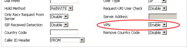
4. Save and reboot the device
Once this is complete you will be able too see the registration status on the web interface:
Using Easy Jack with DSL High-speed Internet
The Easy Jack will not transmit DSL signals so cannot be used for connecting high-speed Internet signals from a phone company or other DSL service provider. However, if you have phone service and DSL Internet from the same provider, the Easy Jack can be used for the POTS (plain old telephone signal) as long as your service provider has given you a DSL filter. The filter will separate the POTS signal so it can be used with an analog telephone device such as the Easy Jack.
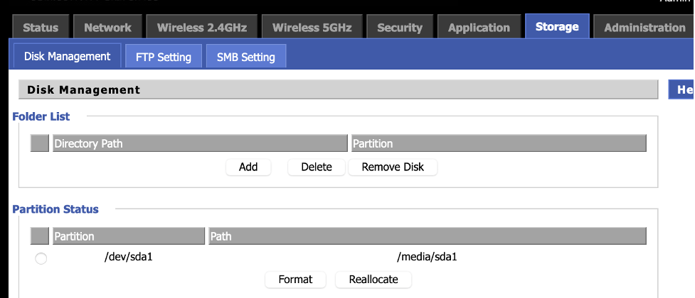
Using the USB Port
The following router models feature a USB port: AC1000, AC1100MSF, AC1200, AC1300, LTE500, QX300, and WR1200. In order to use a USB drive with your router, your USB drive must be FAT32 formatted. Disks with the NTFS file system are not supported. Insert your FAT32 formatted drive into the USB port of the router and login to the web interface. Navigate to Storage > Disk Management. If your USB drive is recognized by the router you will see it listed in the Partition Status section as in the screen shot below:
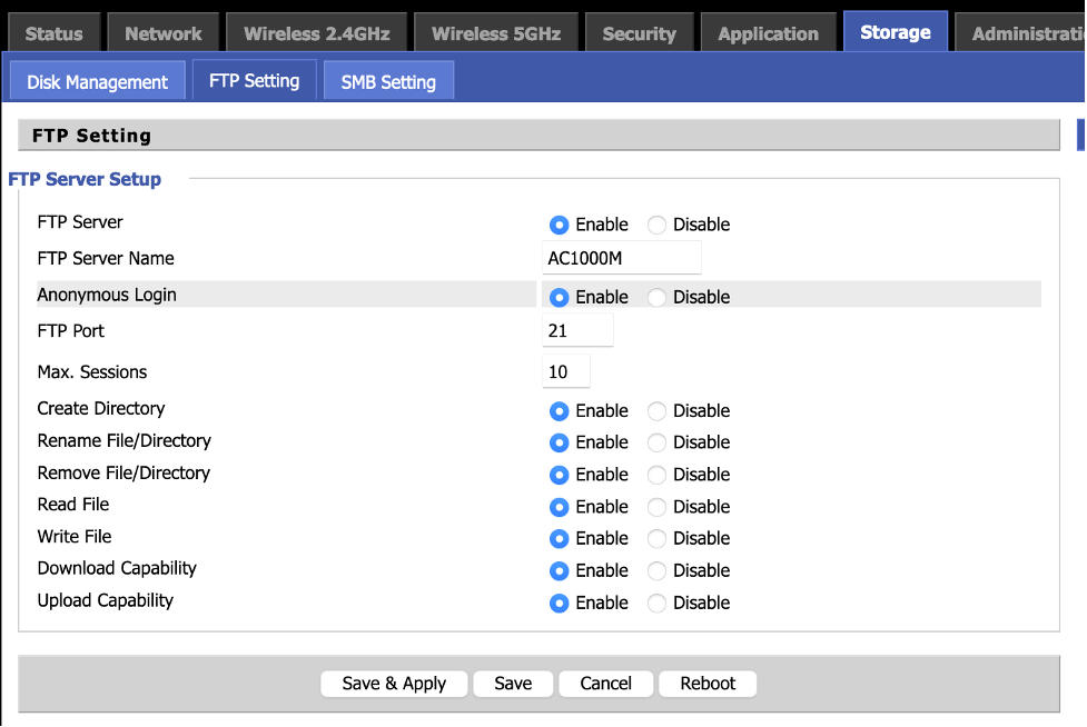
To configure access to the USB drive from devices on your local network, navigate to Storage > FTP Setting.
Set
FTP Server to Enable. To access your USB drive without a password, set
Anonymous Login to Enable. If you set
Anonymous Login to Disable, then you will need to enter the username and password you set for the router to access the contents of the USB drive. Click
Save & Apply to activate your changes.
To access the files on your USB drive from devices on your local network, open the following URL with your browser:
ftp://192.168.11.1 or ftp:// followed by your router's IP address if different. The IP address can be found on the bottom of your router.
(if you disabled Anonymous Login you will be prompted for the username and password of the router)
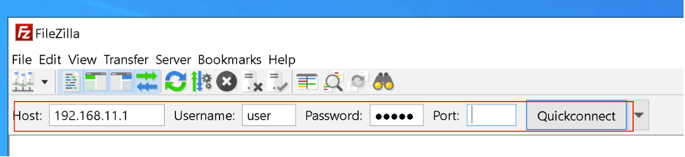
To upload files to the USB from your device you will need to install an FTP application. FileZilla is a free FTP client that you can use if you would like to upload files and folders to your USB.
The screen shot below shows how you can configure FileZilla to connect to the USB that is connected to you router:
VoIP Call Disconnects, Ghost Calls
To correct for VoIP call disconnections, ghost calls and other similar issues, configure your VoIP router to communicate with only the VoIP proxy server as follows:
1) Log in to your router and make a note of the IP address in the field FXS1 > SIP Account > Proxy Server.
2) Set the field FXS1 > SIP Account > SIP Advanced Setup > Only Recv Request From Server to ‘Enable’.
3) Enter the IP address from Step 1 in the field FXS1 > SIP Account > SIP Advanced Setup > Server Address
4) At the bottom of the page, click on Save. Repeat these steps for FXS2 if it is in use.
5) Click on Reboot to apply the saved settings.
VoIP Rings Spontaneously
To address this issue configure the following two settings. These two settings are in the section FXS{n} >SIP Account > Line {n} > Advanced, of the web interface of the AC1200MS. See the following screenshot.

This instructs the device to only accept INVITE packets from the defined IPs. The device will ignore scripts that run probing of all publicly accessible IPs for open port 5060. When this happens, the device rings spontaneously.
By changing these two settings: 1) no unnecessary ring sounds and 2) increased security.
The process above shows you how to do this manually and is good for testing. To automate this, you can have an auto-configuration server append two additional configuration directives;
DBID_SIP_CHECK_INCOMING_IP_ADDR=1 1 0 0
DBID_SIP_ALLOWED_IP_ADDRS=PROXY_IP PROXY_IP
Note 1: Replace ‘PROXY_IP’ with the IP of your VoIP proxy server ( FXS{n} > SIP Account > Proxy Server).
Note 2: Values i.e.
PROXY_IP PROXY_IP
1 1 0 0
must be separated by tabs.
Wi-Max and ReadyNet Routers
If your Wi-Max device provides an Ethernet hand-off, that Ethernet connection can be used to connect to the router, otherwise the router will not associate wirelessly with the Wi-Max device.
WPS Disabled By Default
WPS is disabled by default on all ReadyNet routers. To enable it, log into the router’s user interface and go to the wireless section. In the D6 router, go to Wireless Advanced and click the Enable WPS box. If you want to use push button setup, click in the box Disable PIN. Then click Apply Changes.
In the DD router, go to WIRELESS>WPS and select Enable; then Apply. If in WPS Config, the option is Disable; then WPS is active on your router. If it is Enable; then click Apply. The WPS PIN is the last line in the WPS Summary section on this page.
To enable WPS in the AC1200M/MS, AC1000M/MS, AC1100MSF, LTE520, or QX300, navigate to Wireless 2.4GHz or 5GHz and then the WPS tab, and set WPS to ‘Enable’ followed by ‘Apply’.
The default WPS mode is PBC (Push Button Control). To start WPS mode, press the Reset or WPS button (they may be the same button) for about 1 sec.
The router is now listening for WPS client connections.
WRT300N-D6 MAC Filter Configuration
1) Log in to the WRT300N-D6 user interface.
2) Navigate to Status>Active Client Table and note the MAC addresses of devices that you want to allow access though your router.
3) Navigate to Advanced MAC Filter and add an Outgoing filter. (In the example below the MAC address of the device to be given access is 3c075442d7ef)

Click Add.
4) Similarly, create an Incoming Filter.

You now have:

5) Change the default policy to ‘Deny’ for both directions (outgoing and Incoming).

6) Repeat steps 2-4 for each MAC address you would like to permit through your router.
Notes:
- You may also change the admin password (Maintenance>Password), Wi-Fi passphrase (Wireless>Passphrase) and SSID (Wireless>Name (SSID)
- The MAC addresses of the Wi-Fi and Ethernet interfaces on a PC are different. If you want to connect your PC using both types of connections, you will need to do steps 3-4 for the Ethernet MAC address and for the Wi-Fi MAC address.
- Once you have added all your MAC addresses, back up your settings file (Maintenance>Backup) so you can quickly restore if settings are lost or reset.